Main page for the 12.5″ Dob project
Steve Bieger is building a 12.5″ DOB with one of our donated mirrors. The project will incorporate a number of ideas and construction techniques from telescope maker Albert Highe. Design criteria and has been formulated and actual drawings have been made. The construction of the system is in progress in such a way so that modifications can be made easily once the scope is initially tested.
It hoped that the resulting design will be easy to transport and assemble/disassemble in the field. The construction is being treated as that of a prototype, however, once the scope has “first light”, it may be reasonably close to a final build. Balancing of the components will need to be done using the real system since no CAD software has been used in the design. However, making the system in a modular way will allow for changes and additions at a later date.
Updates
The commentary and photos included here are as of Feb. 7, 2010. Check for updates over the coming weeks as the assemblies get fitted and photographed. There will be a separate page with diagrams and links giving a schematic look at the scope.
Overview of the design
The mirror was donated to the club along with several components of a fill Newtonian Reflector, minus the tube. The mirror is an f6 and if incorporated into a traditional reflector tube, the length of the scope would be some 77 inches long. So, it would seem the best idea would be to build the scope using a truss tube assembly and indeed this was the first line of reasoning in the design draft. The hardware is readily available although a bit expensive. Nevertheless, this seemed to be an ideal construction method at first glance.
One of the major design criteria of this Dobsonian is the ability to disassemble the scope so that the system can be transported in a smaller car. When looking further into the truss design, it quickly becomes clear that the trusses themselves are fairly long. Even a rough guess on the length of all the components still left one with a truss tube length well in excess of four feet. Even if the remainder of the scope can be disassembled, there is still the issue have having to carry and protect the truss tubes. Not an easy demand for a small car.
In looking for other ideas, there was a bit of luck to be had. Sky and Telescope magazine had run an article by Albert Highe showing some of his brilliant ideas and manufacturing techniques. This first article was about a portable scope he had built with a 12 inch mirror. The workmanship was stunning but he was not using a truss tube design. He was using parallel aluminum tubes on the order of an inch and a half. The tubing was attached to wooden bulkheads or rings using a spring loaded insert that was threaded for a common machine bolt. nother article of his found later showed how such a system might be broken down using multiple sections.
This has lead to the idea of a “partitioned OTA”. The mirror box is a more conventional square design, however, the connection to the remainder of the scope is done with parallel aluminum tubing instead of the more common truss tube system.
The “partitioned OTA” design
Instead of having one long assembly to make up the OTA construction, this Dobsonian will have divide up the sections into partitions. Each partition consists of a ring on each end connected together with three or four aluminum tubes. The top partition is made of Ring A and Ring B, connected by 3 aluminium tubes and two or three wooden struts. The top partition holds the secondary and spider assembly and the focuser assembly; both are semi-permanently attached but can be dismantled in the field. The mirror box assembly forms the lower partition and is connected to the other sections with a similar array of aluminum tubes.
Depending on how far the user wants to disassemble the scope in the field, the system can be partially taken apart. The top partition can be separated from the lower partition by removing just three aluminum tubes. The lower partition containing the mirror box can be further broken down by removing Ring C from the mirror box itself.
Manufacturing the partition rings
Each of the partition rings are a different shape. Templates are made using graph paper at full scale using a set of master curves developed for the various radii. The shape is traced out on the plywood along with center lines that will be used to mark the needed drill holes.
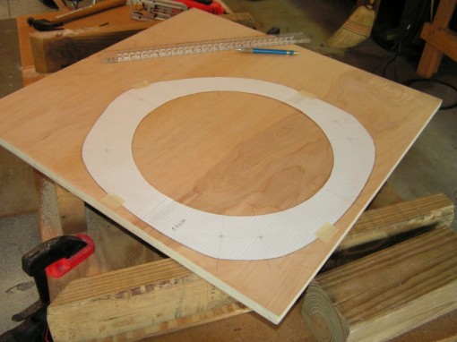
Ring cutout template on the plywood stock
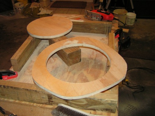
Rough cut of the ring in progress
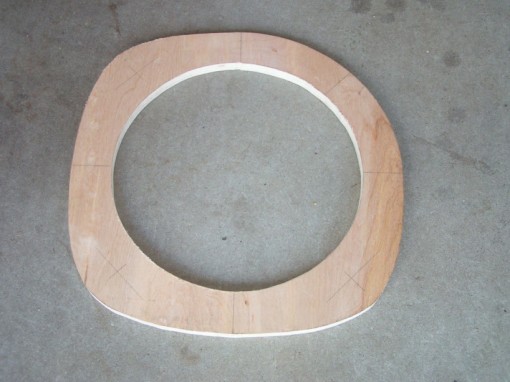
Sanded ring marked and ready for drilling
Using Aluminum Tubing for Struts
This is a close up of one end of a tubing piece with the threaded insert in place. The mounting bolt and fender washer is also shown.
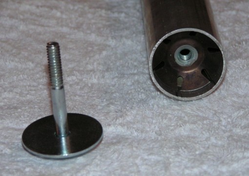
Threaded tube insert and mounting bolt
The mounting bolt is attached with out the fender washer to allow the assembly to be measured. The threaded insert can be pushed further into the aluminum tube to get an accurate position. Of course since the insert cannot be pulled out of the tube, this last positioning must be done carefully.
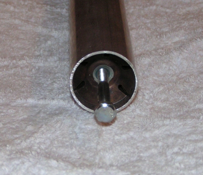
Mounting bolt in place for final measurement
Assembly of rings and aluminum tubes
The end of the aluminum tube will be attached to one of the mounting rings or bulkheads. The attached plywood will be drilled to accommodate the mounting bolt. A slight countersink will also be driller in the plywood to allow the fender washer to sit in a centered position without shifting.
(pictures coming to show this in detail)
Adapting the mirror cell
This view shows the mirror cell positioned on the rear bulkhead. The cell mount bracket is shown bolted into one of the three mounting posts.
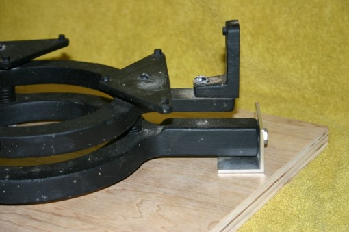
Cell mount bracket and rear bulkhead
(more to come)

