Hello everyone.
The Truss Tube is almost complete! At this point the only thing left to do is to reassemble it, mount the optics, mate it to the Byers mount and collimate. I’ll also have to do some balancing and I’ll probably need to make some mount adjustments depending on how it performs.
The assembly was painted satin black, to give it that anodized aluminum “industrial” look. For accent I covered the outside edges of each truss ring with unpainted, 1/8″ aluminum.
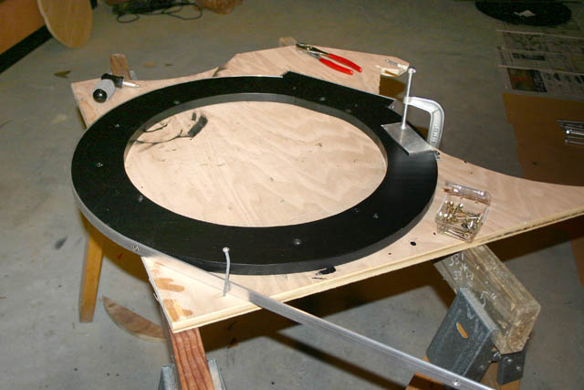
Adding the aluminum strip turned out to be a bit more of a challenge than anticipated. Although the aluminum bends relatively easily, it was difficult to hold everything together while drilling screw holes. So I resorted to clamps and a nail to finish the job.
The image below shows the 4 rings with the edge dressing in place. For the flat areas, I used a single piece with a mitered cut, leaving just enough aluminum to allow a right angle bend without breaking. These “U” shaped pieces are then attached with 2 screws.
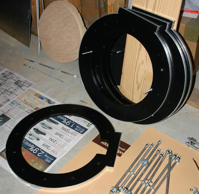
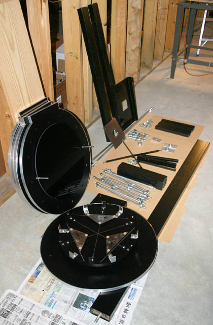
This is a view (below) of most of the parts, ready for assembly. You’ll notice the rings and primary cell near the top of the image and all the various pieces of hardware required to hold everything together below that.
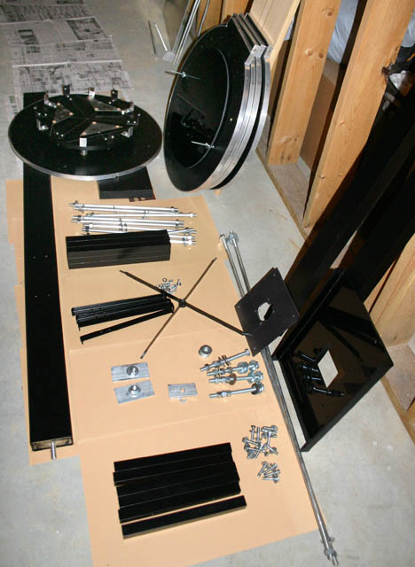
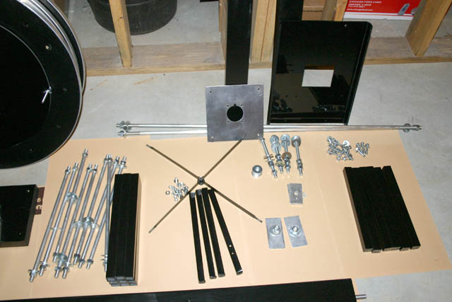
This is a closer view (below) of most of the parts of the truss tube. In the upper right you’ll notice the Plexiglass focuser plate. The aluminum plate to the left of that is part of the focuser plate and will attach to the Plexiglass in 1 of 2 positions to change the amount of back focus. This is necessary for the use of CCD cameras or digital SLR’s with the scope.
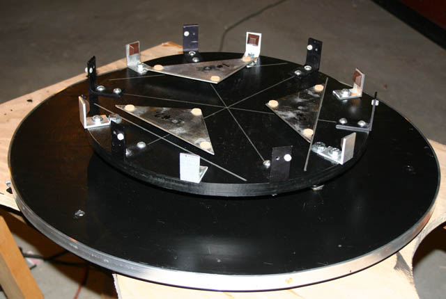
The image below is a shot of the “9 floating-point” cell for the 16″ primary mirror. This cell reuses some of the parts of the original Meade Starfinder Cell, but has additional edge support, larger collimation springs and the floating points were repositioned using “Plop” (software for designing mirror cells).
This shot (below) is another look at the various parts of the assembly. Notice that one of the rings (standing upright to the left) has a cover with 2 long screws extending outward. This is actually a Plexiglass dust cover for the primary mirror. The cell will extend through this ring when assembled and the Plexiglass will attach with 2 wing nuts to protect the primary mirror.
First light for the optical tube will be soon. I’ll keep everyone posted.
Dark skies, Larry Owens
