Hello everyone – here’s an update for March 2010 – First Light!
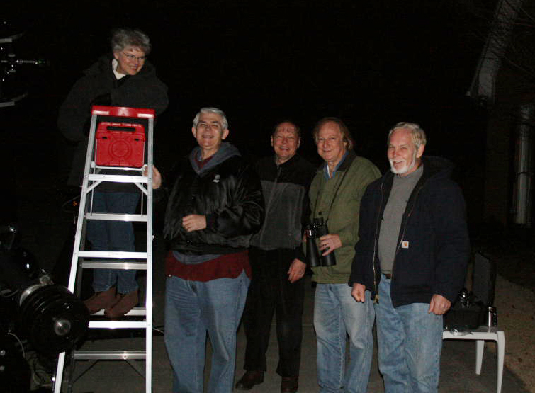
With a new DEC motor in place and operating on the Byers mount, we decided to have “first light” on the evening of March 6th, 2010. Attendees included Clevis and Debbie Jones, Theo Ramakers, Ken Poshedly, Shankar Iyer, my wife Suki and me of course, Larry Owens.
.
.
Our first look through the scope was of the planet Mars. For comparison we also had the C14 setup and trained on the red planet. My first glimpse through the 16″ was at low power, but the limb of the planet did seem unusually crisp to me. Increasingly higher powers revealed a remarkable level of detail. At about 450x the albedo features and the north polar cap were right there, crisp and easy to pick out. The limb of the planet was sharp and well defined, in fact the overall contrast of the image was excellent to say the least. The word “wow” kept creeping into my mind, in fact I can’t remember ever seeing such a crisp planetary image through an eyepiece in my 45 years as an amateur astronomer (an honor previously held by the C14).
I then took a quick look through the C14 at a similar power and the contrast and detail that I saw through the 16″ was just not there. The image was good of course but lacked that spark that the 16″ produced. I checked the collimation on the C14 a few nights earlier, and it was spot on so I think this is just a case of a slightly larger aperture, and expertly refigured and coated optics on the part of John Hudek at Galaxy Optics (give John your business – he does excellent work!).
Later that night we compared views of Saturn through the 2 scopes, and the results were the same – the 16″ offered a much more pleasing image.
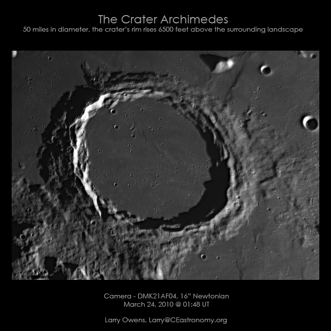
This past week, while testing a new focuser with the DMK camera, I was able to take the first image with the new reflector. The Moon was up, and as a large and easy target, I was just planning to check back focus and to make sure the camera would come to focus using a new barlow. That worked, and as you can see below, I decided to take an avi of the crater Archimedes. This is not a bad image, and it’s straight out of Registax, no PhotoShop work except for the captions.
.
.
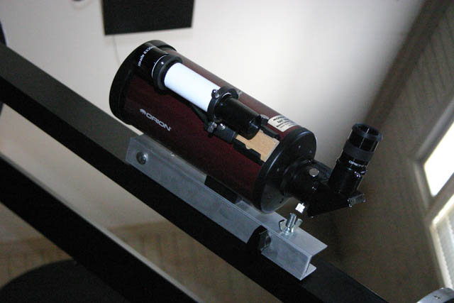
One of the problems we had with the big scope that first night was the difficultly in getting the planets in the eyepiece. This was of course because we hadn’t attached a finder scope or Telrad. So, to remedy that situation, I requested one of the chapter’s 2 Mak’s, and added that as a finder scope for the 16″. The Mak actually has a finder of it’s own, and both in combination make centering the planets in the eyepiece relatively easy now.
.
.
The 4″ scope was mounted on one of the aluminum trusses with a mounting system I’d fabricated for a finder scope on the C14. It pivots left and right, and adjusts up and down with a spring loaded wing nut for alignment with the main scope.
.
.
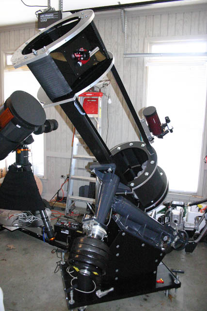
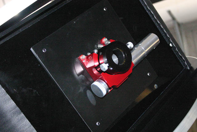
Above you can see where the finder scope is mounted, and you’ll also notice a new “red” focuser at the eyepiece. The focuser is a Moonlite CR Newtonian Crayford device with servo motor. It seems to work rather well, it certainly looks impressive. As you may remember, I modified the original Meade rack and pinion focuser for use during our first light experience, but it was apparent that night, that imaging with the big scope would not be possible without a better focuser.
.
.
As you can see, the servo motor and gear system extends out to the right and also has the connection for a hand controller. The focuser has a 1.75″ travel and the focuser itself is only 1.5″ high.
.
.
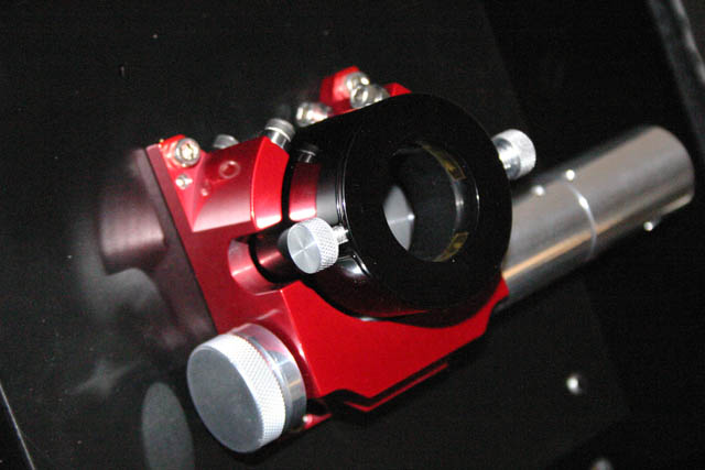
Above is a closer view of the Moonlite CR focuser. The fit and finish are excellent, and the hand controller provides a means to adjust the focus speed for coarse and fine focusing needs. The focuser also has collimation screws to get a perfect alignment with the optical axis.
.
.
Now, shifting gears a bit I wanted to show a couple of images of a technique for centering the secondary and to discuss collimating the big scope.
.
.
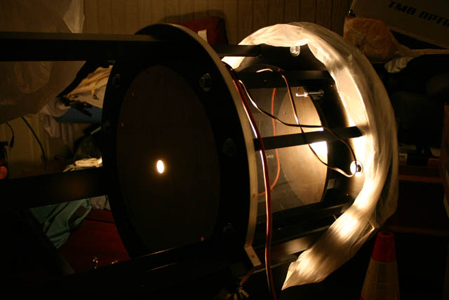
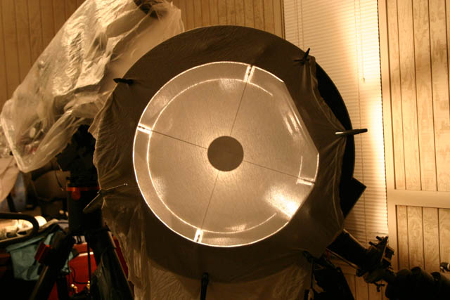
This strange contraption (above) isn’t an industrial laser about ready to fire, it’s actually a simple way to center the secondary in an irregular tube, such as a truss tube. The tiny round light source in the image above is actually in the center of the of the optical path in the lower truss cage of the 16″. It’s constructed using one of the plywood truss ring cut-outs, with a center light hole.
.
.
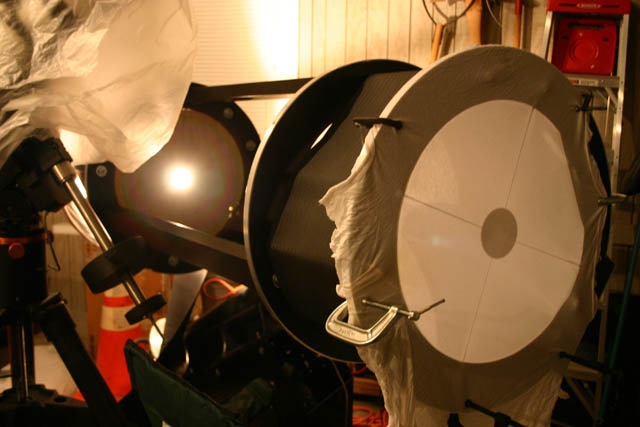
The light source casts a perfect shadow of the secondary on a piece of cloth, stretched across the front of the scope. Now, the reason I went to this much trouble, is that centering the secondary in the tube is fairly important, yet it’s very difficult to measure when the secondary may not be exactly centered in the spider cell and when the spider resides inside a tube constructed of rods and rings.
.
.
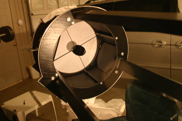
After placing the light source in the lower cage, it’s a simple matter to measure and adjust the position of the spider, using the shadow of the secondary and the inside edge of the upper cage ring. As mentioned, this cancels any error that may have occurred when mounting the secondary on the cell, and provides an easy measurement of secondary offset (or centering – which ever you prefer).
.
.
After adjusting the position of the secondary, it was time to collimate. I collimated the scope using a sight tube and a Cheshire. The sight tube is used to adjust the angle of the secondary, and a Cheshire is used to perform the final collimation.
Collimating the big scope using a Galaxy Optics mirror is actually fairly easy – no need to make a center mark. Galaxy marks the optical center of each mirror with a tiny etched “+”. This shows up rather nicely in the dark center of the Cheshire in a well lighted room or outdoors during the day.
After collimating for the first time, I checked for collimation drift with the scope at various viewing angles to test the OTA and primary cell. It does drift just a bit, so I collimated so that it drifts through perfect collimation as the scope approaches the vertical. Possible causes are the cork mounting pads I used in the primary cell, or there may be some flexiture in the tube assembly. So, I’m planning to systematically make some changes to see if I can fix it. It doesn’t seem to be bad enough to cause an issue, but I’d like to know the cause just the same.
.
That’s it for now. A little planetary imaging is next… I have high hopes for the results.
Dark skies,
Larry

